Mesh Pop-Up Menu
A pop-up menu is available in the Data Settings and Properties to provide access tools for smoothing meshes, creating deviation maps, and adding scalar information, as well as for exporting meshes and executing macros. You should note that the items available in the pop-menu are dependent on the number of meshes selected — single or multiple.
The following items are available when you select a single mesh in the Data Properties and Settings panel.
The following options are available to modify and transform meshes.
Apply Transformation From… Applies transformations, such as translations, rotations, and scaling, that were applied to a reference object to the selected data (see Applying Transformations from Other Objects).
The following options are available to align meshes.
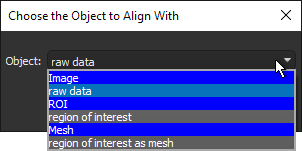
Centroid With… Automatically aligns the centroid of the selected mesh with the centroid of another object. Applicable objects include volumetric image data, regions of interest, multi-ROIs, and other meshes. Reference objects can be selected in the Choose the Object to Align With dialog, which is shown below.
Create an Anisotropy Vector Field… Lets you create a 3D model of anisotropy, in which color scales represent magnitude or direction and density is configurable (see Creating Anisotropy Vector Fields from ROIs and Meshes).
The following options are available for creating new box shapes from meshes (see Adding and Editing Shapes).
Current Bounding Box… Automatically creates a box that corresponds to the dimensions of the selected mesh. If required, you can edit the geometry of the box.
Current Clip Box… Automatically creates a box that corresponds to the dimensions of the selected mesh's clip box. If required, you can edit the geometry of the box.
The following options are available for exporting meshes.
Mesh to File… Lets you save meshes in a number of different file formats suitable for 3D printing and other purposes (see Exporting Meshes in Mesh File Formats).
Export as ORSObject… Exports meshes in the Dragonfly Object (*.ORSObject extension) file format (see Exporting Meshes in the Dragonfly Object File Format).
Mesh to File with Color… Exports meshes in the VRML (*.wrl extension) file format with colors preserved (see Exporting Meshes With Colors).
Opens the Measurement Inspector panel (see Evaluating Scalar Meshes with the Measurement Inspector).
Provides a shortcut for selecting macros that can be executed for a mesh (see Recording and Playing Macros).
Opens the Analyze and Classify Measurements dialog, in which you can import scalar data from meshes and other objects for the cross-table analysis of feature vectors (see Analyzing and Classifying Measurements).
Opens the Compute Measurements dialog, in which you can compute measurements and add other values to a mesh (see Computing Measurements for Meshes).
Lets you assign a new unit to scalar values (see Assigning Units to Scalar Values).
Lets you delete selected measurements from scalar meshes (see Deleting Scalar Values).
Lets you export selected measurements from scalar meshes to a comma-separated values (*.CSV extension) file (see Exporting Scalar Values from Meshes).
Lets you import scalar values contained in a selected comma-separated values (*.CSV extension) file to the selected mesh (see Importing Scalar Values from CSV Files).
Lets you map the scalar values from another object, such as an image, multi-ROI, or scalar mesh, to the selected mesh (see Mapping Scalar Values to Meshes).
Lets you copy selected measurements contained within a scalar mesh to the selected mesh (see Copying Scalar Values to Meshes).
Opens the User Data dialog, in which you can view detailed object descriptions, as well as add fields to further describe the selected objects (see Managing User Data).
Opens the Mesh Decimator panel, in which you can reduce the number of vertices, edges, and triangles in a mesh (see Decimating Meshes).
Opens the Mesh Smoothing panel, in which you can smooth meshes with a selected method and number of iterations (see Smoothing Meshes).
Opens the Mesh Subdivider panel, in which you can increase the resolution of the selected mesh by dividing its triangles into smaller units (see Subdividing Meshes).
Opens the Mesh Registration panel, in which you can register a selected mesh with a reference (see Registering Meshes).
Calculates the deviation (distance) between two sets of meshes (see Generating Deviation Maps).
Calculates the deviation (distance) between two sets of meshes (see Generating Deviation Maps).
Calculates the vertex normal deviation between two sets of meshes.
Note A vertex normal is the average of the face normal vectors of all the faces that share the vertex.
Calculates the vertex normal deviation between two sets of meshes.
Note A vertex normal is the average of the face normal vectors of all the faces that share the vertex.
Lets you compute the number of non-manifold edges in a selected mesh. This function can be used to verify that a mesh does not contain any edges with more than two faces attached to it. You can use this option to evaluate the integrity of a mesh that will be used for 3D printing.
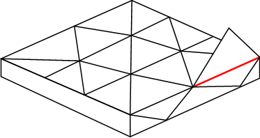
As shown in the example below, non-manifold topology polygons have a configuration that cannot be unfolded into a continuous flat piece. This condition, in which more than two faces share an edge, is known as multiply connected geometry.
Non-manifold edge (in red)
- Right-click the mesh you need to analyze and then choose Get Non Manifold Edges Count in the pop-up menu.
The results are computed automatically and appear in the Mesh Information dialog, shown below.
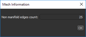
You should note that a value of 0 indicates that the mesh does not contain any non real-world geometry.
Automatically changes mesh winding from clockwise to counter-clockwise or vice versa. This may be required to improve the visualization of capped meshes in 3D views.
Lets you add random vertex measurement to the selected mesh. The name of the measurement and the minimum and maximum values can be entered in the Name and Value dialogs, respectively.
Lets you automatically align the axis of inertia of the selected mesh with the axis of inertia of another mesh.
Automatically computes and adds normal angles from the Z-axis.
Lets you apply linear transformations to the selected scalar value(s) by modifying the slope and/or offset values.
Automatically computes and adds scalar values of curvature calculated with the Gaussian method.
Automatically computes and adds scalar values of curvature calculated with the Mean method.
Lets you obtain thickness values from the mesh of a single, closed 3D shape (see Computing Ray-Tracing Thicknesses).
Automatically computes and adds scalar values of distances calculated from the mean position of a series of points.
Note You must first create a points series with the Point tool to enable this item (see Using the Points Tool).
Automatically computes the Euler characteristic number of the selected mesh.
Lets you reconstruction triangular meshes from sets of oriented 3D points (see Remeshing with Poisson Surface Reconstruction).
Copies the selected mesh. Copied meshes will appear as new items in the Data Properties and Settings panel.
Lets you update the spatial scale of a mesh to obtain the correct values for measurements (see Spatial Scale Calibration).
Extracts the object's history as a macro, which can provide an audit trail to help troubleshoot processing issues (see Extracting Object Histories).
Note Object history macros can also be edited and replayed to create new objects.
The following items are available whenever you select two or more meshes in the Data Properties and Settings panel.
The following options are available for exporting meshes.
Export as Multiple ORSObjects… Exports each selected item as a separate file in the Dragonfly Object file format (*.ORSObject extension) to a selected folder (see Exporting Objects). You should note that if the selected objects share the same name, their file names will be appended with a sequential number.
Export as ORSObject… Exports all selected items in a single file in the Dragonfly Object (*.ORSObject extension) file format (see Exporting Objects).
Provides a shortcut for selecting macros that can be executed for the number of items selected (see Recording and Playing Macros).
Lets you update the spatial scale of meshes to obtain the correct values for measurements (see Spatial Scale Calibration).
